Publications
VACUUM DISPERSION AND MILLING TO IMPROVE SPEED, QUALITY, AND COST
Published in Ink World Magazines April 2021 Issue
Vacuum dispersion is nothing new. Manufacturers have been using vacuum during the dispersion process for years by pulling vacuum on the dispersion tank while running disperser blades or agitators in feedstock tanks. There are many reasons for pulling vacuum on dispersion feed tanks, mainly to keep oxygen and moisture out of the dispersion. In most cases, vacuum is used in reactors during processes that require no oxygen or inert gas to fill the tank to keep the reaction from occurring. Examples include making moisture cure products or hot melt adhesives that need to be clear and air-free when the batch is complete.
Vacuum for the most part has been overlooked when it comes to pigment dispersions because of the added purchase and maintenance expenses of vacuum-capable equipment. A few of the expensive parts of a vacuum system are sturdier vacuum tanks, seals to hold the vacuum, “O” rings on tank lids, dome lids on tanks, and vacuum pumps. For standard pigment dispersions, it did not make sense to pay extra money for vacuum equipment unless necessary. Why pull vacuum on a pigment dispersion and pay extra for equipment and maintenance if you can make the batch using a standard atmospheric disperser? Perhaps what has not been fully considered is the total return on investment when using vacuum dispersion.
Considerations we made when building vacuum dispersion and milling equipment at an affordable price included:
• What are the advantages and disadvantages
• Why is it so expensive?
• What can be done to cut equipment manufacturing costs?
• Can we make affordable equipment that works under vacuum?
• Can we build this equipment?
• Will it work better than standard atmospheric equipment, and if so, how can it be done?
As with most R&D projects, answering these questions started with 3D drawings, raw materials, used equipment, outside-of-the-box ideas, and lots of testing.
FIRST STEPS TO VACUUM MILLING
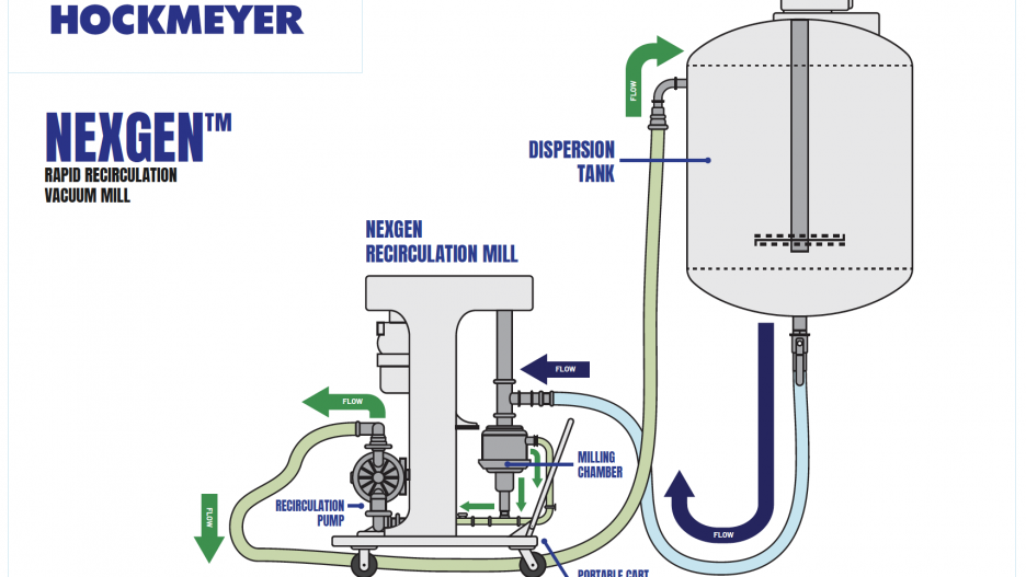
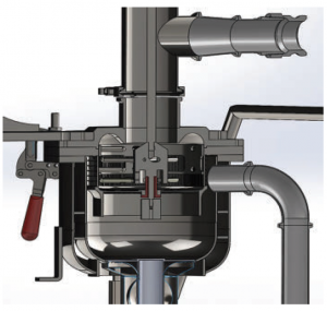
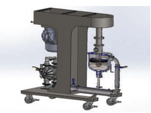
The project started by addressing the vacuum milling process. Existing equipment in the lab was evaluated, and we determined what was needed to get the Immersion mill under vacuum. The milling machine itself already had an optimized design; it just needed to work under vacuum. We started with the smallest mill we make, the MicroMill. Next, we needed a way to seal the mill in some type of chamber that we could pull a vacuum. After some design and fabricating, we had a vacuum chamber that sealed to the MicroMill. Next, we needed to pull the vacuum and transport the feedstock through the mill chamber and back to the feedstock tank. The Immersion mill was one of the first basket-type media mills on the market. It did not need pumps and hoses; it produced its own vacuum using a propeller in the lower draft-tube to pull the feedstock through the media field. The problem with vacuum milling was that the lower propeller no longer had the ability to pull the material through the media field because of backpressure in the return lines going back to the feedstock supply tank. Using a diaphragm pump will pull tremendous vacuum on tanks, therefore we decided to put a diaphragm pump inline to keep the product moving. However, we still did not have vacuum. The next step was to seal the upper part of the mill chamber and then control the feed rate with a valve, which worked well.
After additional testing and refinements, we had a MicroMill inside a small chamber under vacuum. We had demonstrated feasibility. The first big saving was now apparent: we are not pulling vacuum on a giant supply tank; we are pulling vacuum on a very small chamber only slightly larger than the mill head.
ACHIEVING GREATER FLOW RATE
The next question was how much flow can we achieve using vacuum rather than pressure similar to horizontal mills or vertical mills. The answer was astounding: the Immersion mill used vacuum produced by a propeller, but the vacuum mill was using the diaphragm pump, which is inherently better at moving liquid than the propeller. This drastically increased the flow rate through the mill head, making it measurable for the first time.
The Immersion Mill MicroMill was designed to run small batches in the one-liter to one-gallon range, and we estimated that the flow rate through the Immersion mill would be in the one-liter-per-minute vicinity. Because of the mill design, we were not able to get an exact number on the mill discharge, as some of the product went through the side screen and some went through the bottom screen. This all changed when we switched to the NexGen™ MicroMill, where both the side screen and the bottom screen are in the vacuum chamber, and there is only one exit. This allowed for an exact measurement. Additionally, the throughput of the NexGen MicroMill increased compared to the Immersion Mill estimate. A one-liter batch of water in the Immersion Mill was estimated to turn over once a minute, which is very fast for a media mill; with the NexGen Mill, we could pump up to 10 liters a minute, which means the batch was turning over 10 times a minute.
PICKING UP SPEED WITH THE NEXGEN MILL
We started testing the NexGen mill on batches using standard media and screen sizes on paints and inks. The NexGen mill is fast, in many cases 50% faster than the Immersion Mill. Why is the NexGen so much faster than the Immersion Mill, and for that matter, much faster than any other mill on the market? For batches with feed rates that are double or triple that of other mills, the time to reach a given particle size will be less. Customers tell us that horizontal mill manufacturers recommend a batch turnover of about 15 times to complete a batch. The Immersion mill was able to cut that time because of the high flow rate through the mill. With the NexGen mill, the turnover rate is even faster because of the improved efficiency of the diaphragm pump versus the Immersion Mill’s
bottom propeller.
REDUCING THE NEED FOR DEFOAMER
One of the first batches testing the new equipment was a water-based ink. When we ran this batch on the Immersion Mill MicroMill at atmospheric conditions, the customer was on site dripping defoamer into the batch to reduce foam, first during the pre-dispersion and then during the milling process. As a side note, the pre-dispersion was only a pre-mix. It is next to impossible to get a pre-dispersion on a water-based liquid ink in a one-liter batch with a standard disperser. Pre-dispersion tip speeds need to be in the 5000 to 6000 feet-per-minute range to get a pre-dispersion with any type of blade, and there is no way to reach those tip speeds in a one-liter tank. We ran the batch, reached the particle size on the Immersion mill, and then switched to the NexGen mill. Following the same steps used in the previous batch, we started milling on the NexGen.
The customer was standing by with the defoamer, but no foam appeared. We kept watching and waiting for the foam and then watched as the batch level started to drop. We looked for leaks in the lines in an attempt to explain the drop in batch level. Large bubbles were coming up out of the return line in the batch as the level decreased. What was happening? When we made the pre-dispersion or pre-mix on the disperser, we filled the batch with air. At the beginning of milling, that air was concentrated in the vacuum chamber. Once the air in the vacuum chamber reached the exit, it came out through the pump in large bubbles, floated to the top of the feedstock tank and broke. This explained why the defoamer was not needed.
WHAT IS HAPPENING ON THE MACRO SCALE?
On the macro scale, we could see that bubbles added to the batch during pre-mix were pulled out during the milling process, but what was occurring on the macro scale? Testing was done to see exactly what happens to air under vacuum. We dispersed air into a clear resin and put it under 20 inches of vacuum to see how the air changes. We observed that air under 20 inches of vacuum increases in size four times versus air at atmospheric conditions. However, still more was going on at the micro-scale.
When dry powder is introduced into water, clumps appear. It is like making pancakes: add the water to the powder and clumps are everywhere. You can stir it with a spoon, but you can never get them all out. If you were to take one of those clumps out of the bowl and smash it, you would find dry powder and air in the middle. The same thing happens with a pre-mix; you add the powder to the water, and you get agglomerates of various sizes. Under vacuum milling, the first thing that happens is all the free air in the batch comes out; this is on the macro scale. Next are agglomerates that are wet on the outside but still dry on the inside and full of air. When these agglomerates pass from the feedstock tank into the mill chamber, they are under vacuum. Because air expands four times under 20 inches of vacuum, when the agglomerate reaches the mill chamber, the air inside is already expanding and pushing on the inside. At the same time, the media field is attacking the agglomerate from the outside, trying to break it down. Once the agglomerate is broken, the air travels out of the mill chamber and accumulates in the vacuum chamber until there is enough to be pushed in front of the exit line and back into the feedstock tank. The agglomerate is now broken apart or cracked, and the micro air bubbles have been released into the batch and are free-floating and accumulating in the vacuum chamber.
Additionally, water and resin fill the void left by the escaping air, so even if the agglomerate is not completely broken down in the first pass, the air is removed and the agglomerate is being wetted out from the inside and the outside; this is on the micro-scale.
NexGen Batches Versus Immersion Mill Batches
That first water-based ink batch was tested side by side with a batch made on the Immersion mill, which passed all QC testing. We did see a difference between the two batches. While the particle size was the same, it took less time to reach that particle size on the NexGen than it did on the Immersion Mill. We also observed differences in gloss, transparency, batch size, and color development. If the particle size of both batches is the same, why is there a difference?
Gloss
The difference in gloss is due to less air in the finished product. When a film forms, air travels to the top of the film and either stays right under the surface of the film or comes to the top and forms cracks during drying. If the bubble stays in the film, it deforms the surface and produces less gloss. Cracks in the film also create less gloss. Another factor was the absence of a defoamer. Ink does not like defoamer, so less defoamer leads to better film formation.
Transparency
The NexGen batch was more transparent than the Immersion Mill batch. Oversized particles create less transparency, and while we reached the same particle size on both batches – according to the NPIRI gauge – it does not tell the whole story regarding particle distribution. The batch on the Immersion Mill passed through the media field fewer times than the batch on the NexGen because of the higher pump rate of the diaphragm pump versus the lower propeller on the ImmersionMill. Even though the batches on the gauge looked similar, the NexGen batch was more transparent – a result of the number of oversized particles in each batch. The higher number of oversized particles results in less transparency. More passes through the mill resulted in tighter particle distribution.
Batch Size
The NexGen batch was smaller in volume than the Immersion Mill batch due to less air in the NexGen batch, which means specific gravity was higher for the NexGen batch.
Color Development
The NexGen batch was stronger than the Immersion Mill batch because the NexGen batch saw the media field many more times than the Immersion Mill batch due to flow rate. Even though the batches looked the same on the NPIRI gauge, what was going on in the background was not measured. The more times the batch comes in contact with the media field, the tighter the particle distribution, resulting in fewer oversized particles and smaller particles, which will create better color development.
Inline Vacuum Dispersion
Media mills are only as good as the pre-mix they receive. The incoming particle size of a pre-mix determines the media size and screen size used on a media mill. If the incoming particle size of a pre-mix is 200 ums, the screen size on the mill has to be larger than 200 ums to let oversized particles pass through. Using our standard Immersion mill with an incoming particle size of 200 ums, we would start with a .27 mm screen (270 um) or a .5 mm screen (500 um). The screen size then dictates the media size to be used, following the rule that the media should be three times larger than the screen slot size. The .27 mm screen would normally run .8 to 1 mm media and the .5 mm screen would run 1.5 mm media and up. With better media and tighter size distributions, it is possible to run media that is only two times the screen slot size. As the media size gets smaller, the screen slot size has to go down, which means the incoming particle size has to go down. For nano-size particle distributions, very small media must be used from .3 mm down to .03 mm media with screen slot or pore sizes to match the media size.
The pre-dispersions for nano-particle distributions have to be smaller than the screen sizes. This means a very good pre-dispersion must be achieved to keep from plugging the screens. A .3 mm media will require a .1 mm screen, which means a pre-dispersion smaller than 100 ums is required to pass through the screen.
Tip speeds on standard saw-tooth disperser blades need to be in the 5000 to 6000 feet-per-minute range to get proper pre-dispersions. The higher viscosity of a pre-dispersion allows users to reach these tip speeds without worrying about over-vortexing and product splashing out of the tank. Lower viscosities require slower tip speeds to keep the product in the tank. This is where a disperser becomes a mixer with lower tip speeds and very little dispersion occurring. The rule of thumb for standard dispersers is that only 30% of the dispersion occurs with particle-to-blade contact and 70% of the dispersion occurs when particles collide with other particles in the dispersion. Therefore, higher pigment solids in the pre-dispersion process increase the chances of particles coming off the disperser blade and colliding with other particles. Higher pigment loading also means that the viscosity of the pre-dispersion is higher, and users can reach higher tip speeds on the disperser blade without over-vortexing or splashing.
It is common in a plant to see 60 or 100 HP dispersers running at very low tip speeds because the viscosity of the batch is too low to reach proper tip speed. This can be fixed with formulation changes. Letdown can be added later during the pre-dispersion cycle to achieve higher solids and higher viscosities. However, this rarely happens. Companies continue doing the same thing over and over with the same poor pre-dispersion results.
INLINE ROTOR STATORSFOR BETTER PRE-DISPERSIONS
How can this problem be elevated? Inline rotor stators are the perfect tool for better pre-dispersions, as low viscosity and low pigment solids are not a problem. Because the rotor and stator are enclosed in a chamber, the tip speed has no impact on the motion of the feedstock in the supply tank. The machine can run at peak speed and still never have an issue with the batch over-vortexing in the tank. Most inline rotor stators are virtually the same; they pull liquids in from the supply tank, send them through some configuration of a rotor and stator, and then send them back to the supply tank. There are many different rotor configurations on the market to do many different jobs, some for emulsions, pigment dispersions, chopping rubber, foods, cosmetics, etc. For this paper, we will talk about pigment dispersions.
Pre-dispersion on an inline rotor-stator is a lot like milling except no media is used. At the start of a pre-dispersion, all the liquid is added to the supply tank before adding pigment. With
inline rotor stators, you can add pigment directly to the disperser tank if there is some supplemental agitation in the tank to pull the pigment into the liquid; if not, the pigment can be directly injected into the liquid stream before the rotor-stator to wet-out the pigment.
Most rotor stators on the market today use vacuum to pull the feedstock into the rotor and then pressure to push the liquid through the stator and back to the supply tank. The batch is recirculated through the rotor-stator until a particle size that is small enough to pass through the media mill without clogging the mill screens is reached. We have developed a new type of rotor-stator that works virtually the same way the NexGen Mill works using vacuum. With the NexGen rotor-stator (HNGRS) (patent pending), a few changes have made a big difference in particle size reduction. These include vacuum, cavitation, tight tolerances between the rotor and stator, vacuum chamber recirculation, dual pumping rotor, rapid supply tank recirculation, high open area stator for high throughput, inline pigment feed, and air removal from feedstock during batch processing.
Vacuum
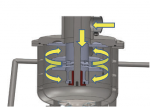
The HNGRS uses vacuum the same way the NexGen mill does. The rotor and stator are enclosed in a small vacuum chamber. The feedstock is pulled from the supply tank under vacuum and enters through the top of the rotor-stator and is pulled down onto the top of the rotor. The rotor spinning at high tip speeds accelerates the feedstock into the upper part of the stator and through the stator into the vacuum tank. The feedstock is then pulled onto the bottom of the rotor and pushed into the stator and through the stator back into the vacuum tank.
Once the vacuum tank is full, the feedstock is pulled out of the vacuum tank and passes through the diaphragm pump back to the feedstock supply tank for rapid recirculation back into the rotor-stator.
Vacuum on the HNGRS is different than vacuum on most rotor stators. As previously mentioned, almost all rotor stators use vacuum to pull the product from the feedstock tank into the rotor-stator. As soon as the feedstock hits the rotor, it goes from vacuum to pressure for the return trip back to the feedstock tank. With the HNGRS, vacuum pulls the feedstock from the supply tank. Once the feedstock hits the rotor, there is a drastic increase in velocity of the liquid, but it is still under vacuum because the entire rotor and stator are enclosed in a vacuum chamber slightly larger than the rotor-stator itself. The feedstock remains under vacuum as it passes through the stator and slams directly into the inside wall of the vacuum chamber. The feedstock never changes from vacuum to pressure until it passes through the diaphragm pump for the return trip to the supply tank. Air is removed from the feedstock and agglomerates are more easily broken down and wetted out because of the voids created when the air is removed.
Cavitation
Cavitation is generated inside the vacuum chamber during dispersion. The rotor and stator are enclosed in a vacuum chamber. As the feedstock enters the top of the rotor, cavitation develops on the rotor. Cavitation can be controlled by the amount of vacuum pulled on the system, using a valve on the feedstock supply tank.
Cavitation is a phenomenon where rapid pressure change creates voids in the liquid where pressure is very low. These voids are short-lived, and when they collapse, they generate a shock wave through the liquid that also helps in particle reduction, much like a sonication disperser.
Tight Tolerances
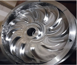
Tight tolerances between the rotor and stator create the perfect environment for particle reduction. There are many different types of shear going on inside the HNGRS: impact, rolling shear, cutting shear, and internal shear from air expanding inside the agglomerates as a result of the vacuum. Tight tolerances between the rotor and stator increase the rolling shear, impact shear, and cutting shear.
Dual Pumping Rotor
The HNGRS is designed with a dual pumping rotor that has veins on both the top side and the bottom side separated by a center plate so that the top veins pump out of the top side of the stator and the bottom veins pump out of the bottom side. This dual-sided rotor provides multiple feedstock passes through the rotor and stator before it leaves the vacuum chamber.
Rapid Vacuum Chamber Recirculation
The rotor on the HNGRS is built to pump from both the top and the bottom. The feedstock is pumped into the rotor-stator from the top. As the vacuum chamber fills up, the bottom side of the rotor starts to pump. The feedstock recirculates through the vacuum chamber and in and out of the bottom side of the rotor many times before it is pulled – still under vacuum – through the outlet and to the pressure side of the pump and back to the supply tank.
Rapid Feedstock Supply Tank Recirculation
The HNGRS is a very rapid recirculation inline rotor-stator. An eight-inch rotor can pump upwards of 300 gallons per minute in water with low vacuum. Recirculation speeds and vacuum work hand-in-hand. Higher vacuum generates lower throughput, and lower vacuum generates higher throughput. The throughput rate is controlled by the supply tank valve and the diaphragm pump rate.
High Throughput Stator
The stator on the rotor-stator is much like the screens on a media mill. For a media mill screen, you want as much open screen surface area as you can get for faster product recirculation. This is also true for the stator on the HNGRS. The H stator design uses interlocking “H” shaped slots for maximum stator open area. The interlocking H slot design gives the stator both vertical and horizontal cutting edges and also plenty of closed surface area for particle collisions when they are coming off the rotor at very high velocity. The clearance between the rotor and stator are very
tight, creating very high shear rates for particle reduction.
Vacuum Pigment Feed
Vacuum pigment feed is an option with the HNGRS inline system. The pigment will enter the liquid stream ahead of the rotor-stator, mix with the liquids, and then hit the rotor and stator for particle reduction. Pigment feed rates depend on pigment type and feed characteristics of the dry powder.
Air Removal from the Feedstock
The HNGRS works under vacuum as air accumulates in the upper part of the vacuum chamber until it comes in contact with the outlet. At this point, the air travels back to the feedstock supply tank in large bubbles and floats rapidly to the top of the supply tank and pops. It is normal to see batches shrink in size during the pre-dispersion process because of air removal.
A combination of better pre-dispersions, with vacuum inline dispersions with the HNGRS, and milling, using the NexGen inline media mill, will greatly reduce pre-dispersion and milling times and the dependency on defoamers in waterbased dispersions.

Barry joined Hockmeyer Equipment Corp. in 1984 when the company moved to North Carolina. He started as a machinist making parts for equipment in the machine shop and welding department, and later on took over plant maintenance and the lab when Hockmeyer started inhouse testing. He was responsible for the day-to-day operations of the lab, client visits for machine start-ups and customer training, Research and Development, and customer testing. Barry has been named on multiple patents for the Immersion Mill, NexGen™ Mill, NexGen™ RotorStator, Porous metal, and polymer screens for nano milling, and he also developed the HPAS 2000 particle analysis system. He graduated from the College of the Albemarle with an associate degree in metallurgical science, drafting, machining, and welding. He is a member of NAPIM (National Association of Printing Ink Manufacturers) and American Coatings Association (ACA). He has given multiple speeches for both organizations on particle reduction and media milling and published papers in PCI magazine, Coatings Technology, Ink World, and other technical journals. Barry is motivated by the challenge to produce equipment that is on the cutting edge of technology. Driven to produce equipment that will produce coatings including inks, paints, automotive coatings, aerospace coatings and wood coatings with smaller particle sizes for stronger color, gloss, transparency, heat resistance, conductivity, weatherability, and appearance, faster than any other equipment on earth for the highest
return on investment for customers.

